Composite Chassis FEA - Context
When I joined the chassis subteam, the composite chassis had not been fully validated under American Solar Challenge (ASC) front, side, and rear impact regulations. In addition, the driver occupant cell geometry excluded most team members due to insufficient length. My role was to develop a complete FEA validation for all impact cases and implement structural and geometric design changes to ensure regulatory compliance while improving driver accommodation and comfort.
Over the course of 4+ months and over 60 iterations across all impact scenarios, I finalized chassis and reinforcement panel designs and documented in our final Vehicle Design Review submission to ASC in January.
Getting the ropes + Process Optimization
Going in with no previous FEA experience, a lot of my time at the start was focused on building a reliable and repeatable simulation workflow. I spent time understanding how to properly constrain and bond multi-component models, accurately representing composite material modeling in ACP using real world testing data, and how to interpret composite failure criteria such as Tsai-Wu and core crush.
A main challenge at this time was learning how to correctly set contacts for multi-component sandwiches and defining contact parameters such as pinball radii.
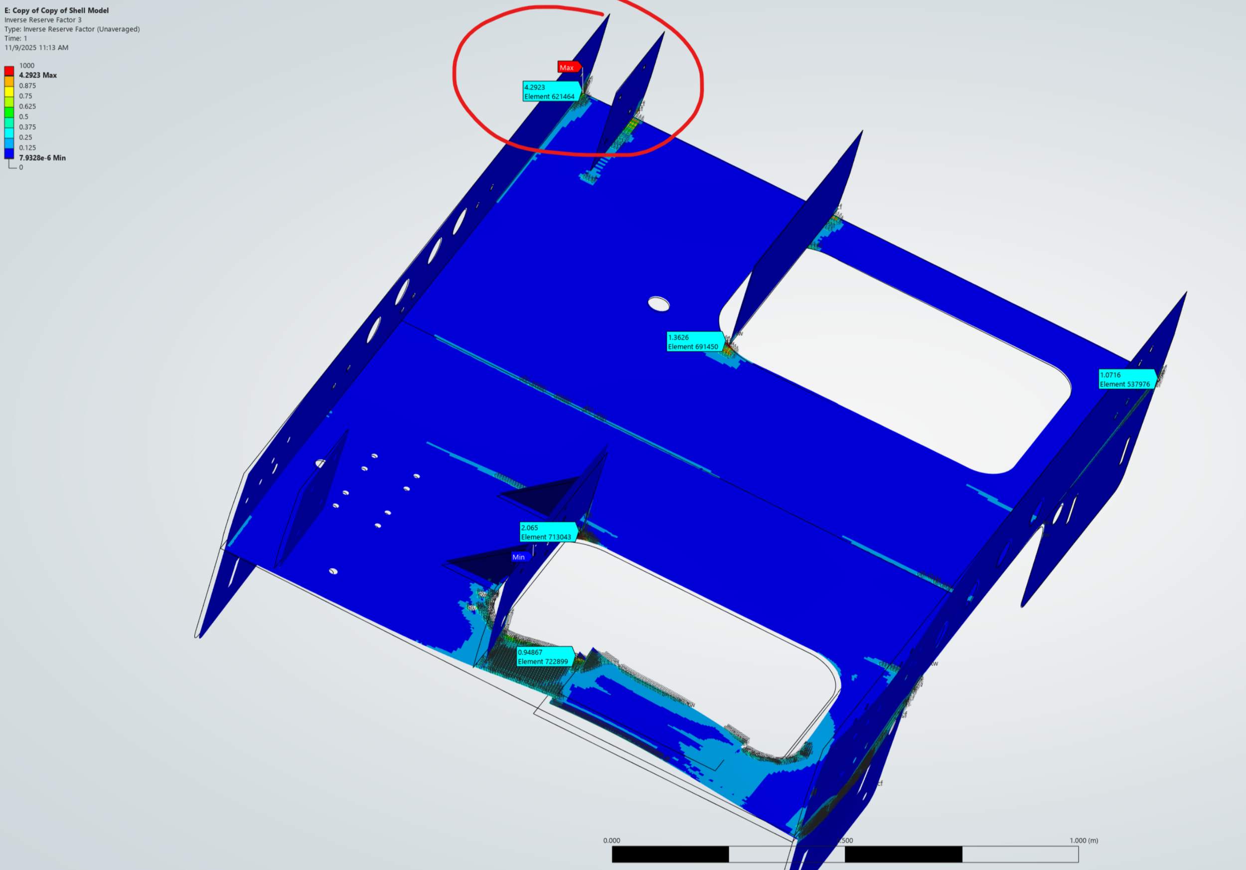
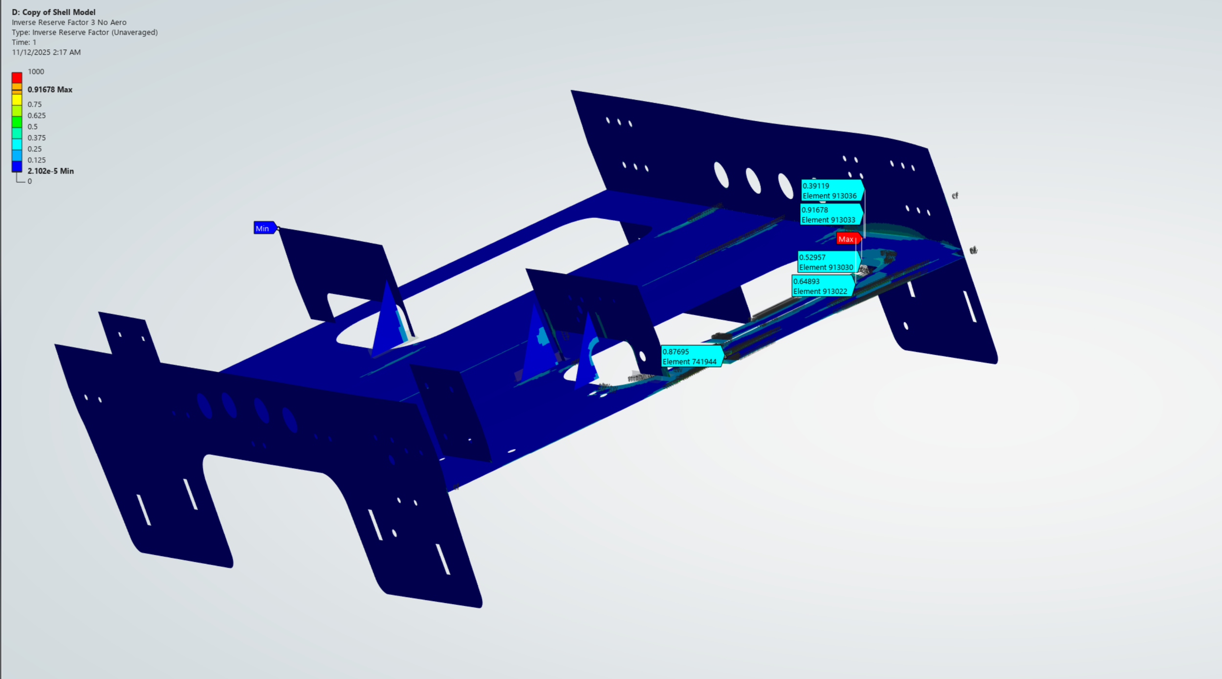
Quickly switched to shell modeling for faster iteration with ~15min solve times
Finalized results using solid modeling after 1st wave of changes before new criteria were established
Made improvements through experimenting with different reinforcement geometries and material layups (weave vs unidirectional, solid “Dragon Plate” vs honeycomb core)
Major Setbacks and Starting Over Quickly
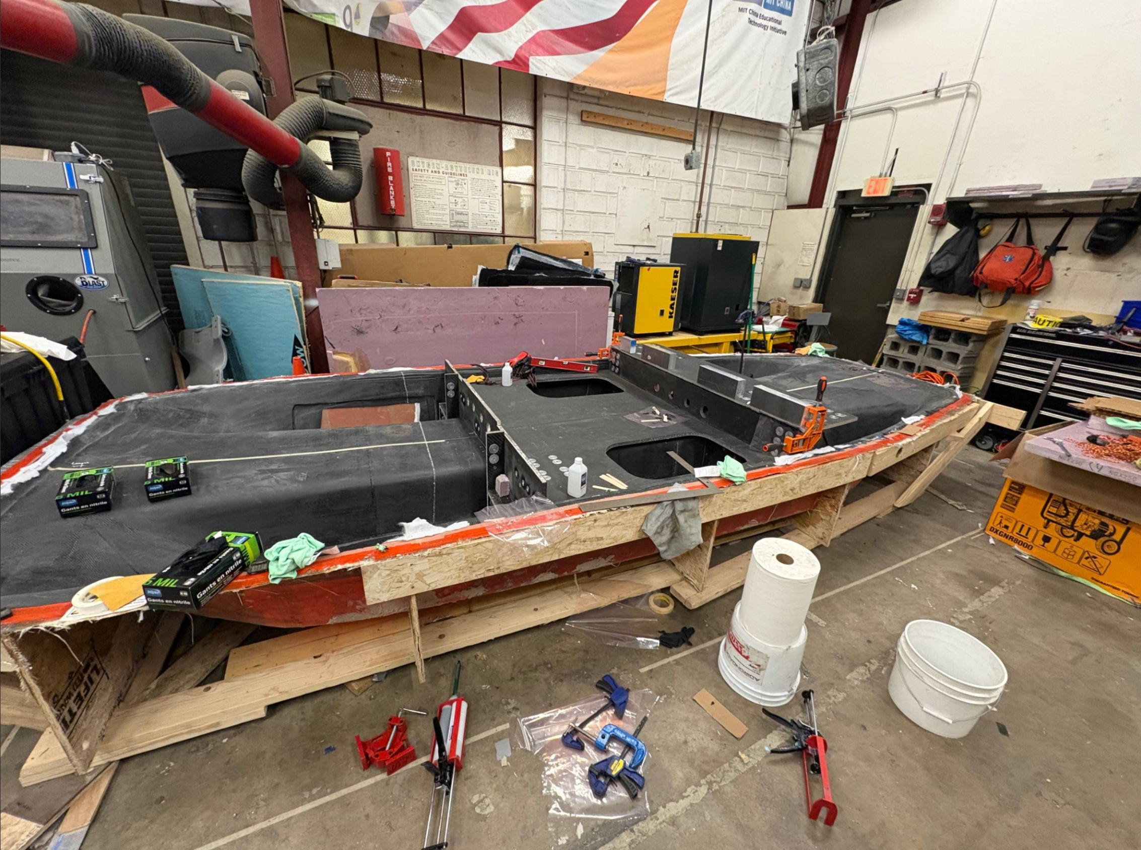
In the middle of water jetting the main chassis panels, two major integration issues surfaced that created major structural problems.
Loss of main structural bond with aeroshell
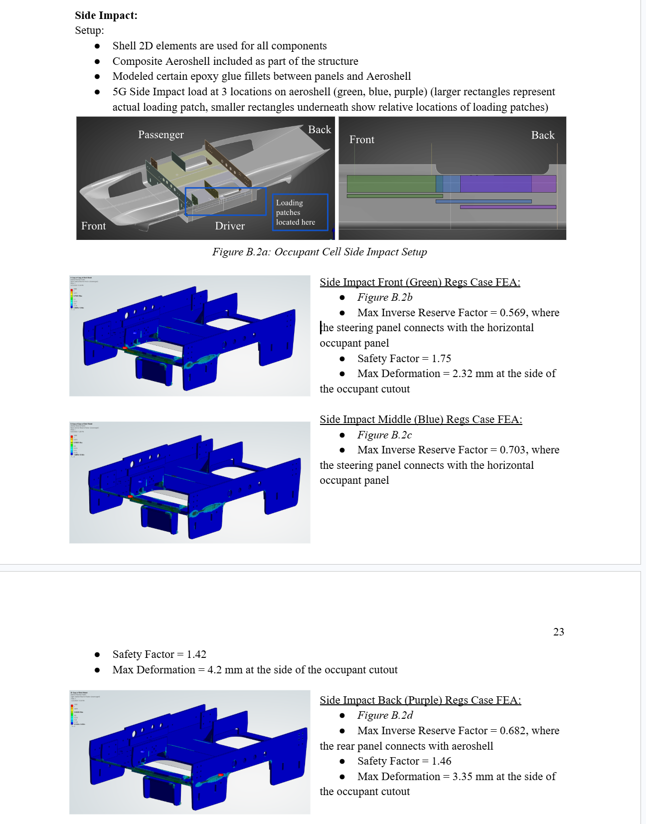
Our externally manufactured bottom aeroshell mold was significantly out of tolerance, creating a gap between the main chassis panel and the aeroshell. To meet timeline constraints, the gap was filled with microsphere thickened epoxy, which is non-structural. As a result, they had to be considered effectively unbonded under impact loading, and making the panel/aeroshell bond susceptible to shear loading from a side impact.
Occupant Cutout Redesign
The original occupant cutout geometry fit our drivers in CAD, but didn’t account for driver leg movement, severely limited the pool of drivers who could fit in the vehicle when a mock cell was set up.
Lengthening and reshaping the cutout reduced global bending stiffness and altered load paths for the three main side impact cases. Removing material in this region increased stress concentrations around the opening perimeter.
Design Response
Because manufacturing was already underway, changes were needed fast and were limited to removing material from the occupant cutout and adding reinforcements using a limited supply of leftover material
To solve this I:
Extended the cutout to add room for leg
Reinforced the perimeter to recover lost side-impact stiffness
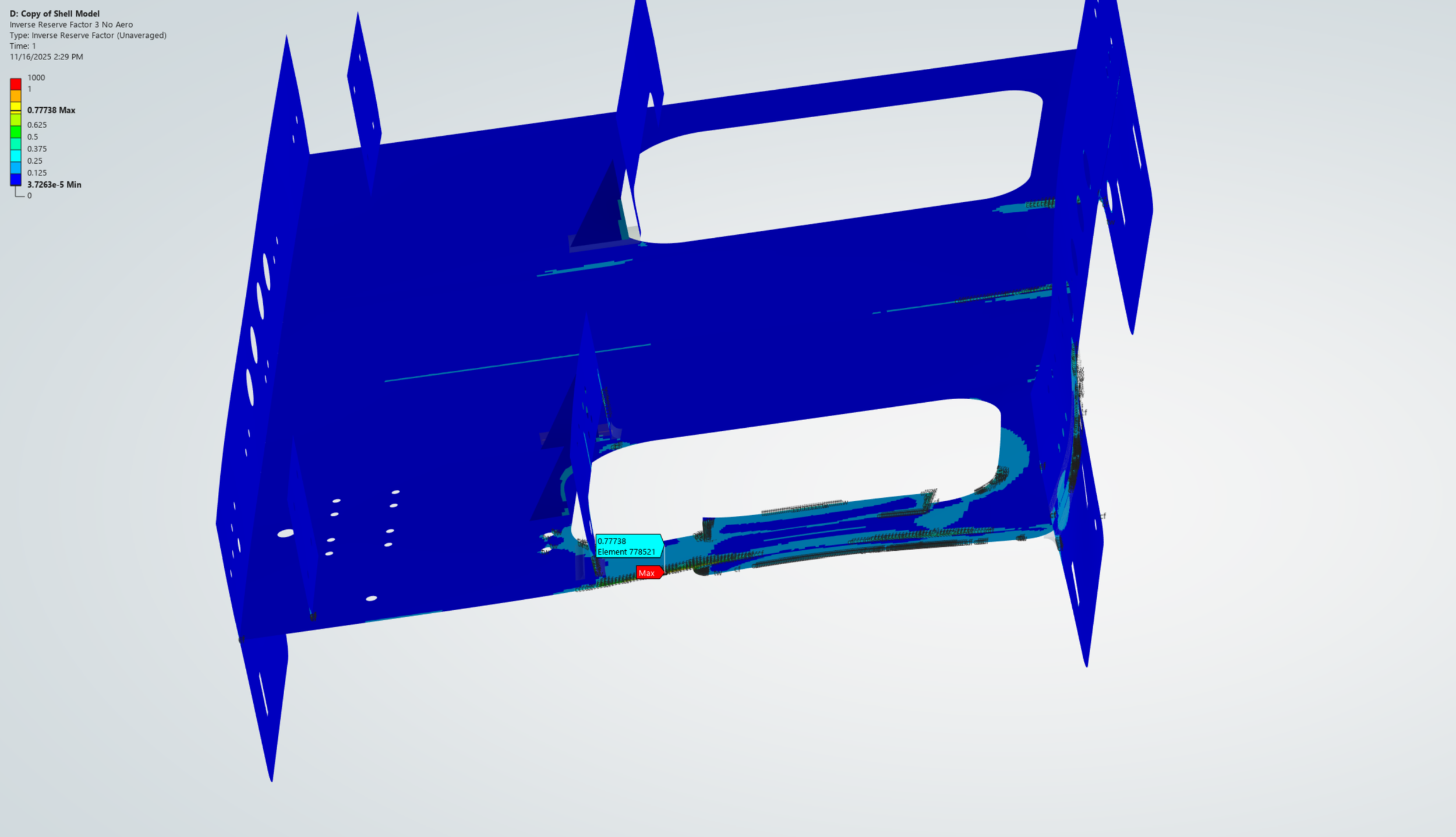
Added reinforcement panels to tie the horizontal chassis panel to the aeroshell without relying on the failed bond
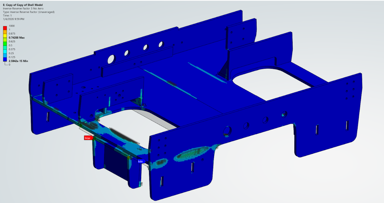
All modifications were revalidated across front, side, and rear impact cases.
Results
Chassis manufacturing proceeded within timeline
New Chassis design fully validated under ASC Regulations before Vehicle Design Review deadline
Further improved chassis safety factor relative to previous design
Increased potential driver pool by over 2×
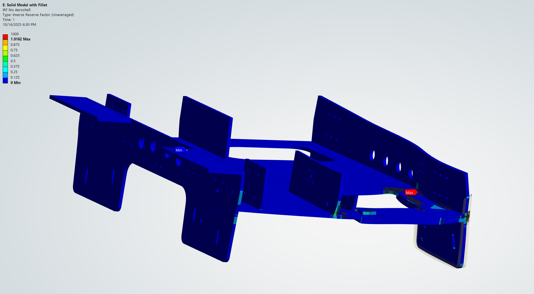
Started with solid models in Ansys - accurate, but required long 90+ min solve times
Initial modifications showed poor results
Finalized chassis during assembly

Final results documented in VDR
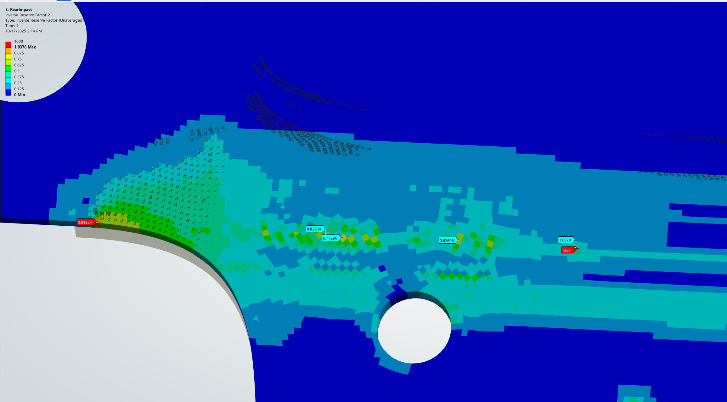
Initially, rear panel, among other areas, consistently showed stress concentrations on the loading patch - needed to add reinforcements + make design changes to address these areas